The primary purpose of this assignment was to design a complete 2.5 Axis motion system. A 2.5 Axis motion system means that the user can control the position in X and Y, as well as the ability to actuate a tool. This differs from a traditional 3 axis system as the user is unable to control the precise height of the tool. A great example of a 2.5 axis system would be a laser jet printer.
The goals of this project were to teach us how to design mechanical framing and joints as well as a basic electrical system. This design forced us to think more than an individual static component, but how to get all of the components working together.
Process:
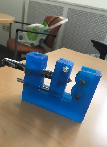
When given this project, we were allowed to look at prior year systems. These systems were big and bulky. Looking at them, I noticed that there was a lot of tension on 3D printed parts, so much that it caused many to warp. As the team opted to use a belt tension system, I thought that the fact that the belt mounting hardware was knocked out of alignment due to this warping, it would cause even more issues, as the system carries weight. So we designed the system to run in the grooves of 8020, attempting to keep most of the force parallel to the direction of motion, and as close to the axis of motion as we could.
In order to do this, we designed many internal faces in the 3D printed carriages, so that we could secure the belt internally. While this design required more time up front, in the long run it saved time as it made calibration and assembly significantly faster.
In addition to special carriages, tensioners were also developed that allowed easy adjustment of the spacing of pulleys. This adjustable spacing allowed even faster assembly and better performance as one could focus on simply quickly slipping on the belt, and then tensioning the belt, rather than trying to stretch the belt over a pre-tensioned pulley system. I intend to reuse the carriage designs, but introduce bearings so that I can increase lifespan and efficiency of the system.
Finally for the end effector, we opted to use a high torque servo motor, we then used pieces of the carriages to enable the whiteout stick to slide up and down effectively. This use of a servo motor to control linear action, caused our system to have a complete 3rd axis! The system is counterbalanced in order to facilitate the use of other tools, as well as to reduce stress on the motor.
Background
Given the use of materials, tooling and machining skills were needed to develop hardware. In addition, a knowledge of Solidworks was used to design the 3D Printed Parts. Finally, simple electronic skills were needed for wire routing
Results & Discussion:
Our device worked as intended! The system easily slid in the 8020, which allowed the 3D printed supports to maintain their form, and keep the pulleys aligned. This system is stable, and even has a fully controllable 3rd axis, complete with counterweight, so less strain is introduced. After some minor calibration issues, this system worked as intended as we had to drive two motors in sync. Looking back, I would like to change the end effector a bit, and maybe add in a light sensor to determine where text is, and have it automatically white it out. In addition, there were a lot of last minute framing additions in order to make the frame more stable and consistent. This system taught me a lot more about working with Solidworks as well as teaching me how to think for 3D printing!
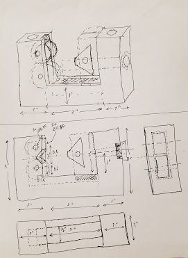
The Designing Phase 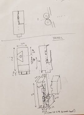
The Designing Phase 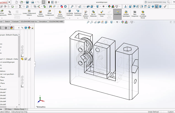
The CAD 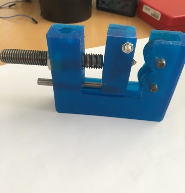
The Finished Product